38 Results
View results:
Sort by:

This article describes and explains the influence of bending stiffness of cables on their internal forces. Furthermore, the text provides information on how this influence can be reduced.
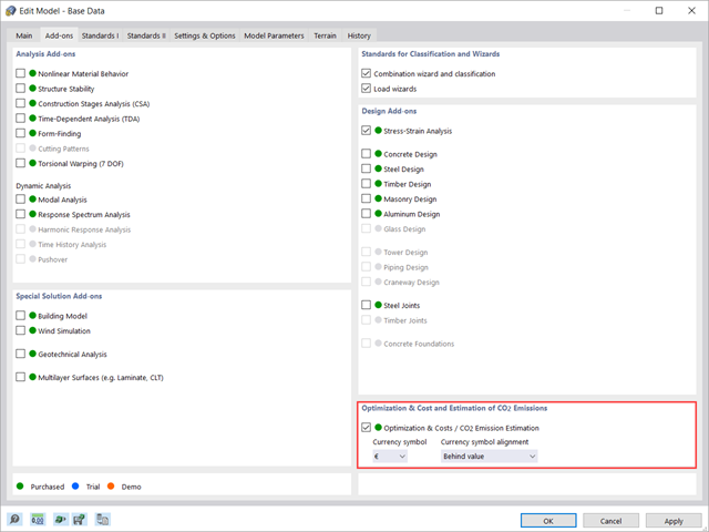
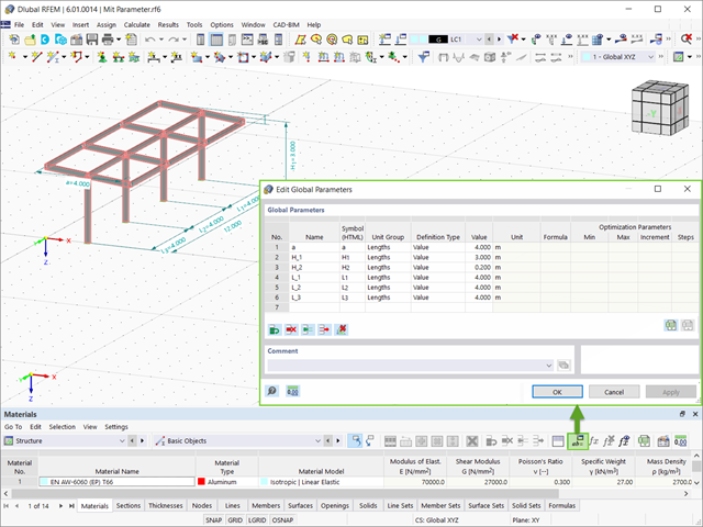
This article shows you how to use the add-on Optimization & Costs / CO2 Emission Estimation to estimate the model costs. Furthermore, it shows you how to optimize parameters based on minimum cost when working with parameterized models and blocks.

Structures in RFEM 6 can be saved as blocks and reused in other RFEM files. The advantage of dynamic blocks with respect to non-dynamic blocks is that they allow interactive modifications of the structural parameters as a result of modified input variables. One example is the possibility to add structural elements by changing only the number of bays as an input variable. This article will demonstrate the aforementioned possibility for dynamic blocks that are created by scripting.
In addition to the predefined models available as blocks in Dlubal Center | Blocks, it is possible to create new blocks and save them in the manner discussed in the Knowledge Base article "Saving Models as Blocks in RFEM 6".

In RFEM 6 it is possible to save selected objects (as well as whole structures) as blocks and reuse them in other models. Three types of blocks can be distinguished: non-parameterized, parameterized, and dynamic blocks (via JavaScript). This article will focus on the first block type (non-parameterized).

The new generation of RFEM software is an intuitive, powerful, and easy-to-handle 3D FEA program that meets all the latest demands in modeling, calculation, and structural design. The modern design concept, as well as the introduction of new features, make the program even more innovative and user-friendly. The main differences between RFEM 6 and its previous version, RFEM 5, are discussed in the following text.
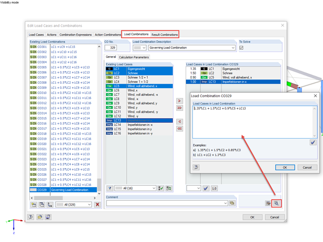
RFEM and RSTAB offer the possibility to edit or check the combinations directly by entering text.
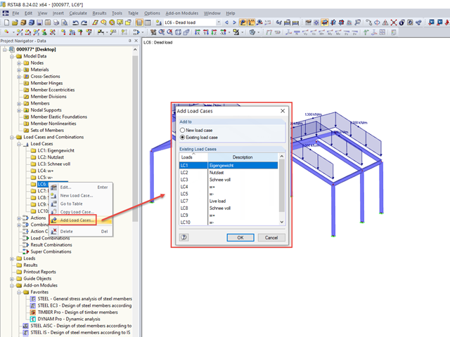
If you want to import a block with previously saved loads into an existing model, the load cases are not integrated into the existing load cases, but are added to the existing ones.
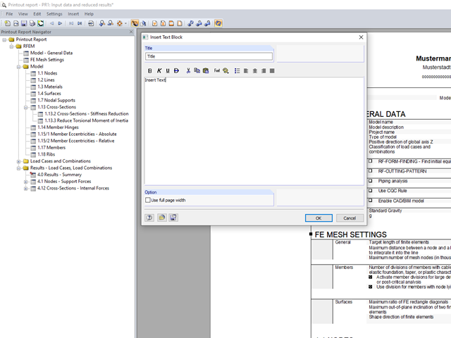
You can insert your own notes in the printout report. To do this, go to the printout report menu and click "Insert" → "Text Block."

You can make various settings in order to achieve a clearly‑arranged display of the result values. For example, some users may not want the white background in text bubbles. You can adjust the background in "Display Properties" using the Transparent and Background color option.
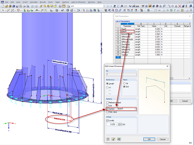
In RFEM 5 and RSTAB 8, it is useful to parameterize frequently occurring components with variable dimensions. In the Block Manager, you then can specify new dimensions and import them in a new or existing file.

In EN 1993-1-1, the General Method was introduced as a design format for stability analyses that can be applied to planar systems with arbitrary boundary conditions and variable structural height. The design checks can be performed for loading in the main load-bearing plane and simultaneous compression. The stability cases of lateral-torsional buckling and flexural buckling are analyzed from the main supporting plane; that is, about the weak component axis. Therefore, the issue often arises as to how to design, in this context, flexural buckling in the main load-bearing plane.
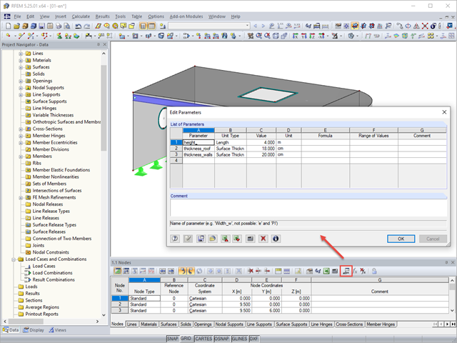
Parameterized entries provide the engineer with an efficiency-increasing tool. This allows entering structural and loading data so that they depend on certain variables. These variables (for example, length, width, live load, and so on) are called parameters.
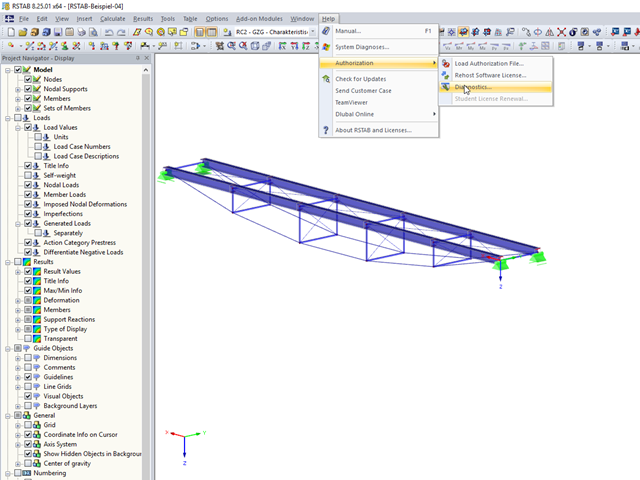
In RFEM 5 and RSTAB 8, you can view detailed information on the currently used license and installed dongle driver. In case of any problems with the license, you can send the created text file to the Dlubal Software hotline, which allows us to provide you with a fast and efficient analysis. To create the file, select "Help" → "Authorization" → "Diagnostics".

The same structures are often needed in several projects, such as the purlin with columns and braces in this example. The dimensions can be changed directly in RFEM or RSTAB by shifting the nodes.
.png?mw=640&hash=8fd04a597cecae2e434980ce79fc626815a5d98a)
The Aluminum Design Manual (ADM) 2020 was released in February 2020. The ADM 2020 gives guidance for both the allowable strength design (ASD) and load and resistance factor design (LRFD) for aluminum members to ensure reliability and safety for all aluminum structures. This latest standard was integrated in the RFEM/RSTAB add-on module RF-/ALUMINUM ADM. The text below will highlight the applicable updates relevant to the Dlubal programs.

RFEM 5 allows you to use many different member nonlinearities for designing a model. In the following text, we look at an example of the use of the "slippage" member nonlinearity. The example is a simplified model of a concrete manhole with a square plan view.
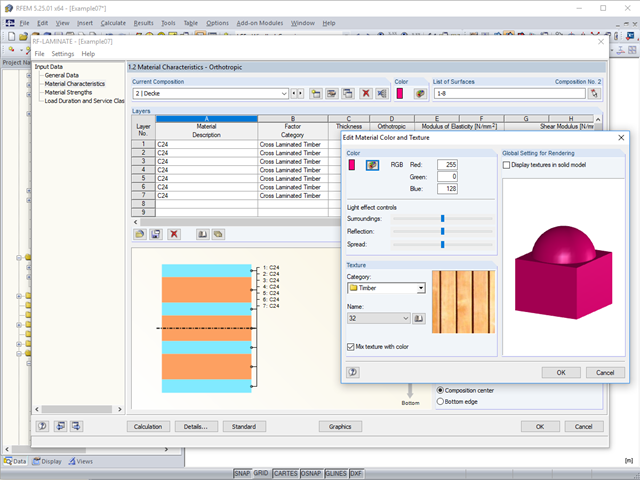
To better distinguish between the different layer compositions (for example, for walls and ceilings), you can assign user‑defined colors and textures to each composition.
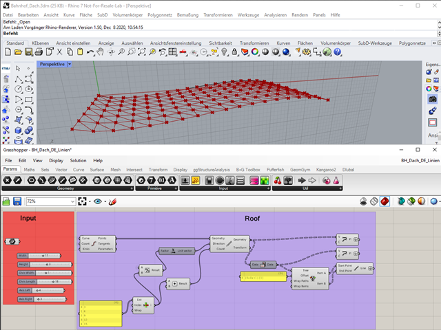
"A good tool is half the job done": This proverb could be applied equally to the software industry. The more a program is task-tailored, the more efficiently the tasks can be solved. The variety and complexity of today's problems, especially in structural engineering, require specifically tailored solutions. Creating your own programs by means of textual programming requires in-depth knowledge and a great ability to abstract. Understandably, only very few engineering offices face this challenge. For this reason, there are additional software solutions providing the user with a visual development environment.
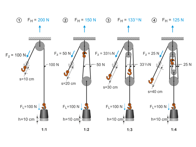
This article describes the basic principles and modeling approaches of pulley systems in RFEM.

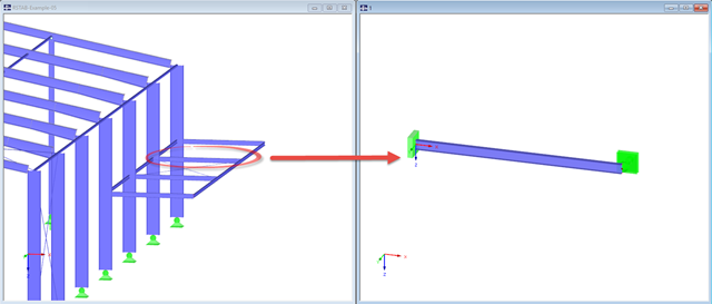
Structures are naturally three-dimensional. However, because it was impossible to perform calculations on three-dimensional models easily in the past, the structures were simplified and broken down into planar subsystems. With the increasing performance of computers and related software, it is often possible to do without these simplifications. Digital trends such as Building Information Modeling (BIM) and new options for creating realistic visualized models reinforce this trend. But do 3D models really offer an advantage, or are we just following a trend? The following text presents some arguments for working in 3D models.

The European standard EN 1993-1-8, Section 4.5.3.3. provides the user with a simplified method for the ultimate limit state design of fillet welds. According to the standard, the design is fulfilled if the design value of the resultant acting on the fillet weld area is smaller than the design value of the weld's load-bearing capacity. Thus, if you want to dimension the weld for a surface model, you will be faced with a variety of results due to the nature of FEM calculations. Therefore, we show in the following text how to determine the force components from the model.
The input windows in RF-/STEEL EC3 distinguish between the flexural and lateral-torsional buckling analyses. In the following text, an example will show the parameters for lateral-torsional buckling.
The cross-section class of a two-span beam will be designed in the following text. In addition, the necessary cross-section designs will be performed. The global stability failure will be excluded due to sufficient stabilizing measures.

The RF-/FOUNDATION Pro add‑on module designs single foundations (foundation plates, bucket and block foundations) for all support forces arising in the RFEM/RSTAB model. The geotechnical designs are performed according to EN 1997-1.
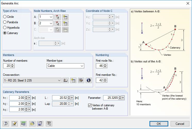
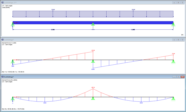
RFEM and RSTAB are able to cover a large number of branches in the building and construction industry with their generally usable structural frame analysis and FEM programs. Designing cable structures is thus also possible in both software solutions. Some assistance tools for modeling and design will be presented in the following text.

Fin plate connections are a popular form of pinned steel connection and are commonly used for secondary beams in steel structures. They can be used easily in beam structures arranged on the top edge (for example, working platforms). Manufacturing expenditures in the workshop as well as the onsite assembly costs are normally manageable. The design seems to be completed easily and quickly, but it has to be put into perspective to a certain extent in the following text. Moreover, this connection type is basically possible as a pinned beam-to-beam or pinned beam-to-column connection; the former case is the more common one in design practice.
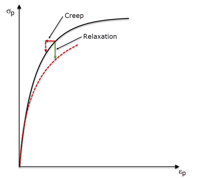
The time-dependent stress losses from creeping, shrinkage, and relaxation have to be considered when designing prestressed concrete components. The consideration of relaxation losses when designing prestressed concrete in RF-TENDON and RF-TENDON Design is discussed in detail in the following text.
.png?mw=640&hash=5852c5c8a1cdb9f021a168d75c0a0466fb430ef7)
Lattice towers represent typical applications in steel construction. Examples of this special type of truss structure are antenna and overhead line towers, as well as columns for wind power stations, cable cars, and supporting frame constructions. The modeling can be done individually in RFEM and RSTAB by entering various tower elements. Furthermore, you can use different copy functions and parameterized input options. However, this procedure normally requires considerable effort. It is more convenient to model such structures using prefabricated catalog elements provided by the Block Manager. These elements are automatically stored in the database during program installation. Thus, you can use tower segments, platforms, antenna brackets, cable ducts, and so on as parameterized building blocks for generating diverse tower structures.
Printout reports created in RFEM and RSTAB can be transferred to VCmaster using a direct interface and further processed there. VCmaster (formerly BauText) is a word processing program for engineers. Calculations, drawings, photos, and documents from various sources can be easily compiled, managed and used again with VCmaster.